Sizing motors you cannot afford: a static analysis story from a student robot arm
When I started the static analysis for a 4-DOF robot arm earlier this year, I assumed the hard part would be the math. It was not. The hard part is what you do when the numbers come back and the motors in the workshop cannot hold the arm up.
This post is about that gap, and the three things I did to close it while dealing with a restricted budget. It is also a short tour of the basic torque calculations themselves, in case you have not done one before and want a worked example.
Context: this was a group coursework project at Heriot-Watt for the B5XRO Robotic Mechanical Systems course, where we designed and built a robotic letter sorter. I led the static analysis, the inverse kinematics, and the motion control software. The full system used machine vision to read names off envelopes and dropped them into pigeonholes. The arm worked.
The setup
A serial robot arm is a chain of links. Each joint has to hold up everything that comes after it, including the payload. The further out a mass is, the more it tries to rotate the joint backward. That rotational pull is torque, and it is what your motor has to overcome just to keep the arm still, before you ask it to move anything.
The standard simplification is to treat each link as a uniform rod, which means its mass acts at the geometric midpoint. For a single link of mass m and length L with the joint at one end, the gravitational torque is m*g*L/2. For a payload of mass m_l at the tip, the torque contribution is m_l*g*L. You add up everything outboard of the joint and you get the holding torque that joint needs to produce.
For our arm, the worst case is fully extended horizontally. That puts every mass at its maximum lever arm.
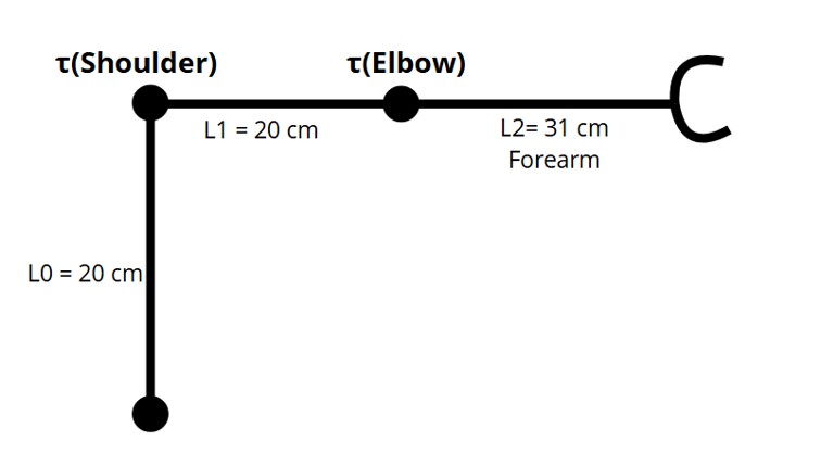
Dimensions and masses, after the first round of CAD:
- L0 = 20 cm (vertical base column, no horizontal lever)
- L1 = 20 cm (upper arm: shoulder to elbow)
- L2 = 31 cm (forearm + gripper assembly, rigidly joined)
- m1 = 510 g (upper arm)
- m2 = 300 g (forearm + gripper)
- m_l = 100 g (max letter mass with margin)
The elbow only has to hold up the forearm and the letter: τ_elbow = m2g(L2/2) + m_lgL2 = 0.39.81(0.31/2) + 0.19.810.31 = 0.456 + 0.304 = 0.76 Nm (≈ 7.7 kg*cm)
The shoulder has to hold up everything past it: the upper arm, the forearm, and the payload. Each one at its own lever arm: τ_shoulder = m1g(L1/2) + m2g(L1 + L2/2) + m_lg(L1 + L2) = 0.519.810.10 + 0.39.81(0.20 + 0.155) + 0.19.81(0.20 + 0.31) = 0.500 + 1.045 + 0.500 = 2.05 Nm (≈ 20.9 kg*cm)
So I needed 0.76 Nm at the elbow and 2.05 Nm at the shoulder.
The problem
I went to the workshop motor cupboard. Here is what was available:
| Motor | Joint | Holding torque |
|---|---|---|
| Futaba S3003 servo | Elbow | 0.32 Nm |
| NEMA 17, 48 mm stepper | Base | 0.41 Nm |
| NEMA 17, 60 mm stepper | Shoulder | 0.64 Nm |
The elbow is borderline. The S3003 gives 0.32 Nm against a requirement of 0.76 Nm. That is less than half the torque needed for this joint.
The shoulder is the real problem. 0.64 Nm against a requirement of 2.05 Nm. If I powered it up in the worst-case configuration, it would stall and the arm would collapse.
A senior engineer with a real budget would buy a bigger motor. We had a small project budget and the workshop’s larger steppers were either in use or not available.
So the question became: how do I make 0.64 Nm of motor torque hold up an arm that wants 2.05 Nm?
Three levers, all pulled at once
There are exactly three things you can do when the motor torque is fixed and you cannot change it.
Lever 1: reduce the lever arm. Shorten the link. Less L means less torque demand, linearly for the link’s own weight and linearly again for everything beyond it.
Lever 2: reduce the mass. Lighter link, lighter payload, lighter everything outboard. Same linear relationship to required torque.
Lever 3: gear it down. Trade speed for torque. A reduction of N to 1 multiplies your motor torque by N (minus efficiency losses) at the cost of N times slower motion at the joint.
I did all three.
Shortening L2
L2 here is the combined length from the elbow to the gripper tip, because the forearm and gripper were rigidly mounted with no joint between them. We did not design the gripper. It was an 11 cm assembly borrowed from the lab, so that part of L2 was fixed. The only length actually under my control was the structural forearm: roughly 20 cm in the initial revision, cut to 8.5 cm in the final.
The forearm appears in the shoulder calculation twice: once for its own midpoint (L1 + L2/2) and once for the payload at the very tip (L1 + L2). Every centimetre off the end of the structural forearm comes off both terms, which makes it the highest-leverage thing I could cut. We landed at a total L2 of 19.5 cm. Any shorter and the arm could not reach across the workspace from the tray to the furthest pigeonhole.
Lightening the links
Two things had to happen. The obvious one was thinning walls and hollowing internal volumes on the 3D printed parts. The less obvious one was figuring out where the motors lived. Every motor outboard of the shoulder counts against the shoulder torque budget at its full lever arm. A 50 g servo at the elbow contributes 0.1 Nm of shoulder torque on its own, before you account for anything else.
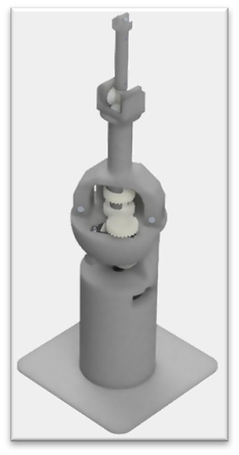
Jonathan proposed a mechanism that pulled the elbow actuator back to the shoulder. The upper arm contains two concentric shafts: the outer one rotates the entire L2 assembly, and the inner one drives the wrist through a 1:1 bevel gearbox at the elbow. Both motors mount at the shoulder, on the rotation axis, where their mass contributes zero gravitational torque to the joint. With the actuators relocated, the forearm became structural-only and dropped from roughly 300 g to 127 g. The upper arm stayed at 510 g because it now houses the shafts and the bearings, but that mass sits much closer to the shoulder than an elbow-mounted motor would, so the trade pays off.
Adding a planetary gearbox at the shoulder
I re-ran the analysis with the new dimensions and masses. The shoulder requirement dropped from 2.05 Nm to 1.13 Nm, the elbow from 0.76 Nm to 0.31 Nm. The elbow now sat just under the S3003 servo’s 0.32 Nm rating, which closed that joint by mechanical changes alone. The shoulder was still well over what the motor could supply.
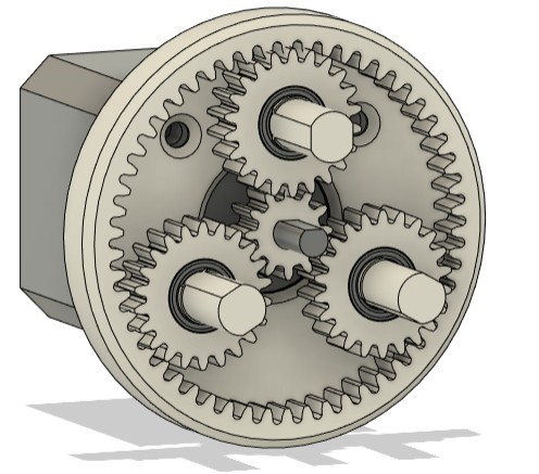
A 1:2 planetary reduction at the shoulder takes the motor’s 0.64 Nm and turns it into 1.28 Nm at the joint. τ_shoulder_available = τ_motor * N = 0.64 * 2 = 1.28 Nm
Against the 1.13 Nm requirement, that is a safety margin of about 13 percent. Still tight by industrial standards, but acceptable for a coursework prototype that runs at low speed in a controlled environment.
The gearbox is not free. There are three real costs:
- Halved joint speed. The shoulder now moves at half the angular velocity it would without the reduction.
- Backlash. A 3D printed planetary gearset has play in it. We did not measure it, but you can feel it. This adds positional error at the end effector.
- Bearings. The planetary set needs four bearings: three for the planet gears and one for the sun. That is extra cost and assembly complexity.
There is also a small software consequence worth noting. A NEMA 17 with 1.8 degrees per step becomes 0.9 degrees per joint step once the 1:2 reduction is in the loop. The firmware needs to know this. The fix is one line but the principle is general: every time you put a mechanism between the motor and the joint, the unit conversion in your motor control code has to change with it.
What did not change: the base motor
The base motor rotates the entire arm about the vertical axis. The arm’s weight acts parallel to the rotation axis, which means it produces no gravitational torque on the base joint. The 48 mm NEMA 17 at 0.41 Nm is fine, it only needs enough torque to accelerate the arm rotationally, not hold it against gravity. This is a useful thing to notice. Not every joint needs to fight gravity.
Two things I would do differently
One. I would do the static analysis before the CAD, not after. I did the analysis once I had link dimensions to plug in, which meant the redesign work came later than it needed to. If I had run a torque budget from rough dimensions on day one, the shoulder constraint would have been visible from the start and the CAD would have been built around it.
Two. I would budget for a real bearing in the planetary set, or look harder at whether a worm gear or harmonic-style 3D-printed reduction would give better backlash characteristics. The planetary set worked, but the play in it is part of why the end-effector positioning was not as repeatable as the math suggested it should be.
The summary
Four numbers tell the whole story:
- Required at shoulder: 2.05 Nm
- Required at shoulder after lightening the links: 1.13 Nm
- Available from motor: 0.64 Nm
- Available after 1:2: 1.28 Nm
The interesting engineering was not the calculation. It was the fact that the calculation forced a series of design changes that propagated everywhere else: shorter forearm changed the reachable workspace, lighter links changed the rotational inertia and therefore the acceleration limits, the gearbox changed the unit conversion in the firmware. A single torque shortfall ended up touching mechanical design, electronics, and software.
If there is one thing to take from this, it is that the static analysis is not a checkbox you tick before you start building. It is a budget you keep coming back to. Every gram you add to the forearm, every centimeter you extend the reach, every CAD iteration that thickens a wall, all of it shows up in the torque calculation.
This was a group project at Heriot-Watt University. CAD modelling was led by Jonathan Higgs, whose iterative weight reduction made the static analysis numbers achievable in the first place.